# STM32F103C8T6 Dev. board
## Overview
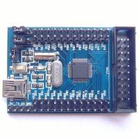
 I have had this board on a shelf for quite some time, but never used it before. Having nothing better to do this week-end, I gave it a try, and here is what I've found/done.
It's a small development board, with a 20 pins JTAG connector, a MiniUSB connector and all (?) pins broken out on two rows on the side.
There's a 8Mhz quartz (with PLL, the chip can run at 72Mhz), a 32.768kHz quartz (for the RTC), and that's pretty much all, but for only 10 bucks… It's okay ![]()
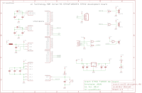
I have found a schematic that looks okay

## Bootloader
The board is shipped without any software, link, datasheet, or pre-loaded code. Luckily, the STM32 family chips often (always ?) embed a bootloader. For this chip, STM32F103C8T6, it's a Serial bootloader, which can be accessed on the top left UART header (the 4 pins next to the USB port).
I have tried flashing it with the SWD (that can be found in the JTAG header) with an ST-link programmer. I does work but requires some hardware. So the Serial bootloader…
Don't forget to set BOOT0 to 1 (and keep BOOT1 to 0) with the appropriate jumper on the board. Then, power or or reset the Board (with the onboard switch) and flash you binary ![]()
[redox@RedoXPS ~/STM32F103_Demo]$ stm32flash -w ./main.bin -v -g 0x0 /dev/ttyUSB0
stm32flash - http://stm32flash.googlecode.com/

Using Parser : Raw BINARY
Serial Config: 57600 8E1
Version      : 0x22
Option 1     : 0x00
Option 2     : 0x00
Device ID    : 0x0410 (Medium-density)
- RAM        : 20KiB  (512b reserved by bootloader)
- Flash      : 128KiB (sector size: 4x1024)
- Option RAM : 16b
- System RAM : 2KiB

Wrote and verified address 0x08001e6c (100.00%) Done.

Starting execution at address 0x08000000... done.
It should start right away. If you're using the USB port in your code, you will probably have to unplug and replug the board from your USB port (or else it won't enumerate…).
## USB bootloader
The serial bootloader is better than the JTAG stuff when you only need to flash your code. However, it requires an USB-Serial adapter, changing jumpers, … Not really friendly. So I looked for another method: an USB bootloader.
Keep in mind that you can easily screw up the USB bootloader, while the serial bootloader is much much harder (impossible ?) to accidentaly erase.
I haven't found many bootloaders that could work without an external switch, … So I settled on a modified version of the Maple bootloader. Another one would have been OpenBLT but the PC software seems Windows-only so… \>_<
The Maple Bootloader provides DFU access. You can program to RAM or Flash. I won't go into details about DFU… On Archlinux, install the dfu-utils package from the AUR, and then it's just “simple”.
[redox@RedoXPS ~/STM32F103_Demo]$ dfu-util -d 1337:1eaf -a 1 -D ./main.bin -R
dfu-util 0.7

Copyright 2005-2008 Weston Schmidt, Harald Welte and OpenMoko Inc.
Copyright 2010-2012 Tormod Volden and Stefan Schmidt
This program is Free Software and has ABSOLUTELY NO WARRANTY
Please report bugs to dfu-util@lists.gnumonks.org

Filter on vendor = 0x1337 product = 0x1eaf
Opening DFU capable USB device... ID 1337:1eaf
Run-time device DFU version 0110
Found DFU: [1337:1eaf] devnum=0, cfg=1, intf=0, alt=1, name="DFU Program FLASH 0x08005000"
Claiming USB DFU Interface...
Setting Alternate Setting #1 ...
Determining device status: state = dfuIDLE, status = 0
dfuIDLE, continuing
DFU mode device DFU version 0110
Device returned transfer size 1024
No valid DFU suffix signature
Warning: File has no DFU suffix
bytes_per_hash=155
Copying data from PC to DFU device
Starting download: [##################################################] finished!
state(8) = dfuMANIFEST-WAIT-RESET, status(0) = No error condition is present
Done!
Resetting USB to switch back to runtime mode
Some changes have been made:
* USB VID/PID have been changed * LED moved to PA0 * LED timings changed * Button removed * Bootloader timeout also changed * It now used a little bit less than 16Kio; the user-program flash definition has to be changed accordingly: it should start at 0x08004000 instead of 0x08000000
Note: With DFU, don't forget to “prepare” your bin file before use:
dfu-suffix -a ./main.bin -v 1337 -p 1eaf -d 0001
The latest source is: maple-based-bootloader_20140414_2306.tar.gz
## Demo
Trying to figure out the bootloaders didn't let me much time, and I didn't have any real application, so I just set up a quick demo, two leds flashing on PA0 and PA1.
The latest source is: stm32f103_demo_20140414_2316.tar.gz made for the USB bootloader
Since the last time I worked with ARM µC, I had a deeper look into RTOS, so I thought I would quickly try one. I settled on ChibiOS, since it's opensource, actively maintained, and I like its name.
Going though the forums, I also noted its little brother Nil RTOS, and a different one Ethernut I might try someday…
Here's a quick demo (two LEDs, different rate): demo_armcm3-stm32f103_20140414_2325.tar.gz.
Download ChibiOS 2.6.3 and extract this archive in the board folder, then cd in it, and _make_ (prepared for the Serial bootloader), and then flash.
## Links
* STM32F103 product page * STM32F103x8 Datasheet (from STmicro, rehosted here) * STM32Book * http://tech.munts.com/MCU/Frameworks/ARM/stm32f1/ * http://www.fussylogic.co.uk/blog/?p=1238 * http://www.emcu.it/STM32.html * http://www.olliw.eu/2013/stm32-this-and-that/ * http://darauble.wordpress.com/2014/01/09/hello-arm-ir-truputukas-teorijos/ Not in english…
