# Teensy 3
## Overview
 I won't get into much details. The official website, PJRC.com, does its job really well.
I already had experience with the Teensy2, but I needed more power, better ADC, … for a larger project (work, can't tell much more sorry)°. Before going for the Teensy3, I reviewed different ARM breakout boards, but I didn't need any special features or a large board.
### Teensy3.1
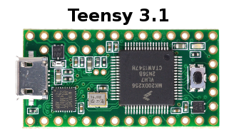 Shortly after I worked with the Teensy 3, PJRC released a new version, Teensy 3.1
No more black PCB, but gold plated finish instead of tin plated. You can't have everything, right ?! It's basically a simple CPU upgrade, but you can find more details on this page.
## Tools
### Arduino vs C Well, the only thing that was not really cool (for me) with the Teensy3 was there was no toolchain, no libraries, no tutorial whatsoever for one to start coding.
Paul, from PJRC, has made a really great work to make the Teensy3 fully Arduino-compatible, but that was not what I was looking for. I wanted to code in pure, bare-metal C, with a GNU/Linux environment. I took me a while to understand the datasheet (1200+ pages of fun !, the Arduino libraries, … and have my code running on the Teensy3.
### Toolchain
Just a quick note, it's really easy. I'm working with GNU/Linux environments, my main workstation is currently running an Archlinux x64. To start developping for ARM you need only two packages, which are in the _community_ repository, so it's just:
sudo pacman -S arm-none-eabi-gcc arm-none-eabi-binutils
That's all folks, you're good to go ;)
On others distros, it should be something really close ![]()
### Teensy Loader CLI
Once again, Paul made a great USB bootloader. It's even better than the one on the Teensy2, since it's harder to brick; actually, there's a second µC on the board, that load the bootloader in RAM when you press the Reset button on the Teensy.
You need the teensyloadercli software, but, obviously, updated for the Teensy3. It can be found in the Teensyduino package). Usage is then really simple:
* Start the application with the correct arguments.
Like ` ./teensyloadercli -mmcu=mk20dx128 -w -v YOUR_HEX.hex`
* Press the onboard button
* Wait until completion
* Done !
## LED Blink Or, as it's often called, the _Hello World_ for µC
Nothing fancy, it just blinks the onboard LED on the Teensy3. The source is here: Tsy3_BlinkLED
Compile with `make` then program with `make program` (you need the teensyloadercli software in the source folder, I moved it system-wide later I think…). Press the button on your board, it should be flashed and then reboot. The LED blinks ! =D
## USB ### HID Debug It should work with the hid\_listen software from PRJC…
Well, blinking a LED is really cool (I _love_ LEDs)° but the Teensy3 is a bit too-much for doing just that. Moving on to USB, I really liked the usb\_debug\_only feature on the Teensy2, so I though I would do something like that for the Teensy3.
Digging through my sources, I found I didn't separate the HID Debug and the RawHID I had to develop for the project I was working on so… no separate source here (yet, I hope to fix that someday…).
Well, I had the occasion to work with the Teensy3.1 (basically the same) so I cleaned up everything and here's a source for USB Debug: tsydebug_20140916.tar.gz
### RawHID
I needed some USB communication, (basically, I needed to send some data from slave devices through USB, in a portable way) so I went for Raw HID. With Full Speed USB, you can send up to 64bytes at once, no driver needed on the computer side, …
The code provides usb\_debug (through the _hid\_listen_ tool) and raw\_hid (tests with the _rawhid_ tool). It's currently available here: TsyUSB_Sept2014
<note important>I found out later that it's not really HID compliant, and then doesn't install correctly on Windows (XP, Vista, Seven). I fixed it in the final project but not in this code. Runs fine under Linux though…</note>
## I2C ### Master <note warning>TODO</note>
### Slave <note important>TODO: Cleanup, explain</note> Well, it's a little bit messy sorry, but it's old code for me; and I don't currently have time to clean things up. Two sources:
* I2C Slave Scan OK
Basic I2C slave, can be detected when scanning the I2C bus
* I2C Slave Buffers
Input/Ouput buffers for I2C data, quite basic though…
## ADC <note important>TODO: Cleanup, explain</note>
uint16_t ADC_Conv(uint8_t ch);
static const uint8_t TsyADCtoARMpin[] = {
	5, 14, 8, 9, 13, 12, 6, 7, 15, 4,
	0, 19, 3, 21, 26, 22};
In your main, at initialization:
        uint16_t x;
		///////////////////////// ADC - Tsy 18, 19, 20, 21, 22, 23 for ADC Inputs
	PORTB_PCR2 = PORT_PCR_MUX(0);															  // PB2
	PORTB_PCR3 = PORT_PCR_MUX(0);															  // PB3
	PORTC_PCR1 = PORT_PCR_MUX(0);															  // PC1
	PORTC_PCR2 = PORT_PCR_MUX(0);															  // PC2
	PORTD_PCR5 = PORT_PCR_MUX(0);															  // PD5
	PORTD_PCR6 = PORT_PCR_MUX(0);															  // PD6

		///// VRef (Chap 33)
	VREF_TRM = 0x60;
	VREF_SC = _BV(7) | _BV(6) | _BV(5) | _BV(0);
	while(!(VREF_SC & _BV(2)));				// Wait for stabilization

		///// ADC Conf
	SIM_SCGC6 |= SIM_SCGC6_ADC0;												// Enable ADC0 Clock
	ADC0_CFG1 = ADC_CFG1_ADIV(3) |												// ADCK = InputClk/8
				ADC_CFG1_ADLSMP |												 // Long Sample time
				ADC_CFG1_MODE(3) |														// 16bit ADC
				ADC_CFG1_ADICLK(1);											 // Input Clk = SysCLK/2
	ADC0_CFG2 = ADC_CFG2_MUXSEL + ADC_CFG2_ADLSTS(0);			  // Channels B, longest sample time
	ADC0_SC2 = ADC_SC2_REFSEL(0); 											// Use default VREF pins

		///// Cal (Follows the Datasheet instructions)
	ADC0_SC3 = ADC_SC3_CAL + ADC_SC3_AVGE + ADC_SC3_AVGS(3);
	while(ADC0_SC3 & ADC_SC3_CAL);

	x = 0;
	x = ADC0_CLP0 + ADC0_CLP1 + ADC0_CLP2 + ADC0_CLP3 + ADC0_CLP4 + ADC0_CLPS;
	x = x/2 | _BV(15);
	ADC0_PG = x;

	x = ADC0_CLM0 + ADC0_CLM1 + ADC0_CLM2 + ADC0_CLM3 + ADC0_CLM4 + ADC0_CLMS;
	x = x/2 | _BV(15);
	ADC0_MG = x;
After the main:
/* In: ADCn pin to sample
   Out: 16bits unsigned result
*/
uint16_t ADC_Conv(uint8_t ch) {
	ADC0_SC1A = TsyADCtoARMpin[ch];
	while (!(ADC0_SC1A & ADC_SC1_COCO));
	return ADC0_RA;
}
In the main, when you need an ADC conversion:
// TempSense is an unt16_t variable; 14 is the Internal temps sensor (fake)channel number
TempSense = ADC_Conv(14);
## PWM <note important>TODO: Cleanup, explain</note>
		///////////////////////// PWM
	PORTA_PCR12 = PORT_PCR_MUX(3)|PORT_PCR_SRE;												 // PA12
	PORTA_PCR13 = PORT_PCR_MUX(3)|PORT_PCR_SRE;												 // PA13
	PORTC_PCR3 = PORT_PCR_MUX(4)|PORT_PCR_SRE;												 //  PC3
	PORTD_PCR4 = PORT_PCR_MUX(4)|PORT_PCR_SRE;												 //  PD4
	PORTD_PCR7 = PORT_PCR_MUX(4)|PORT_PCR_SRE;												 //  PD7

	SIM_SCGC6 |= SIM_SCGC6_FTM0|SIM_SCGC6_FTM1;							 // Enable FTM0, FTM1 Clocks

	FTM0_CNT = 0; FTM1_CNT = 0;														// Initial Value
	FTM0_MOD = 0xFFFF; FTM1_MOD = 0xFFFF;			  // Top Value. 48MHz/TopValue = PWMfreq = 733Hz
											   // MSnB:MSnA = 10, ELSnB:ELSnA = 10, Edge-aligned PWM
	FTM1_C0SC = 0x28;																		 // PA12
	FTM1_C1SC = 0x28;																		 // PA13
	FTM0_C2SC = 0x28;																		 //  PC3
	FTM0_C4SC = 0x28;																		 //  PD4
	FTM0_C7SC = 0x28;																		 //  PD4
	FTM0_SC = FTM_SC_CLKS(1) | FTM_SC_PS(0);				  			//  Use SysCLK, divided by 1
	FTM1_SC = FTM_SC_CLKS(1) | FTM_SC_PS(0);
	FTM0_MODE &= ~FTM_MODE_WPDIS; FTM1_MODE &= ~FTM_MODE_WPDIS;

	FTM1_C0V = 32767; //Example
## Links
* Bare-metal Teensy 3.x Development. Featured on Hackaday, which reminded me I still hadn't published my own code/experience… * cmason/teensy3 - Bitbucket Some neat work with the Teensy3, helped when I started (and with the USB stuff too…)